
Welcome to our Frequently Asked Questions (FAQ). Here you can find technical informations, suggestions and warnings about the correct choice and usage of power plastic film capacitors.
Application and technical support for the correct choice and use of Icel film capacitors
In this section we offer an application and technical support that, in addition to the parametric search, help to choose the right capacitor. A powerful and effective tool to make the better choice for your business.
Main applications for Icel film capacitors
The main application fields of products are: UPS, INVERTER/CONVERTER, MOTOR CONTROL, WELDING, BATTERY CHARGER, INDUCTION HEATING, MEDICAL, TRACTION AND GREEN ENERGY (FOTOVOLTAIC, EOLIC).
DC-Link capacitors are essential, for example, in inverters and switching power supply circuits
The main function of a DC-Link is to balance the instantaneous power variations between the input source and the output load
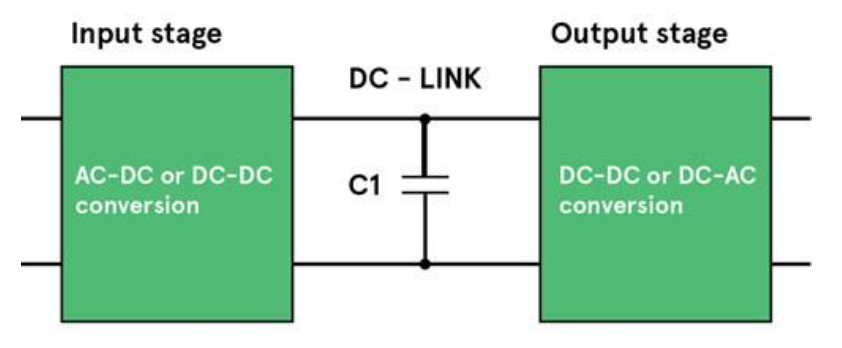
In applications from the simplest cell-phone charger to grid-tied inverters operating at hundreds of kW, power conversion schemes are used which incorporate an intermediate stage where energy is processed at DC
A DC-link capacitor is fitted at this point to provide
- low impedance path for high frequency switching currents
- energy storage
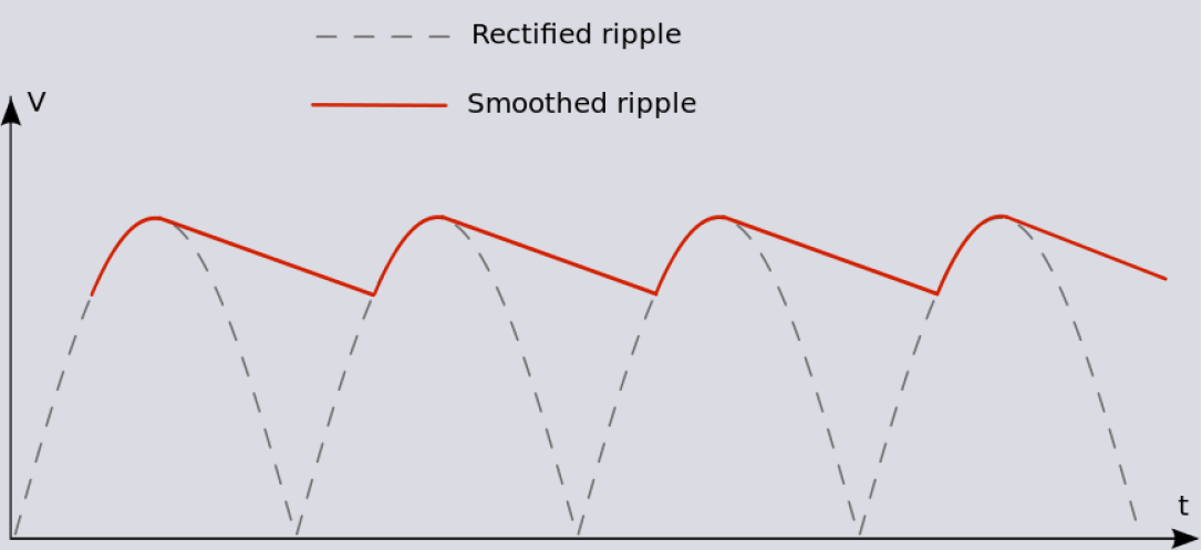
- output filter, absorbing switching currents for minimum ripple voltage
In a switching power supply, AC power is converted to DC without passing through a transformer, and fed to a highfrequency power oscillator. The DC-link capacitor is applied after rectification
In a power inverter, a DC link capacitor is placed in parallel with the input to minimize the effects of voltage variations as the load changes
The spikes generated by the power device (switching on and off) need to be effectively decoupled to minimize heat and best protect the power devices; very low equivalent series resistance (ESR) and low self-inductance are required. The other critical performance specification is ripple-current.
The most commonly used DC-Link capacitors are:
- Electrolytic capacitors
- Plastic film capacitors
In general aluminum electrolytic capacitors are used in power electronics due to their very high power density. However, in an increasing number of applications plastic film are selected as they show some fundamental advantages:
- higher rated voltage
- very low dissipation factor and equivalent series resistance (ESR)
- very high insulation resistance
- higher tolerance to power surges
- wider temperature range
- considerably higher reliability by outstanding self-healing properties
- long life expectancy
- non-polarized construction
- high vibration and shock resistance
- excellent mechanical stability
Most DC-Link plastic film capacitors are designed with polypropylene metallized film material. It is a low-loss dielectric material, suitable for designing capacitors for use in both low and high pulse applications.
The properties of a plastic film capacitor are significantly dependent on the construction technology used, but a good DC-Link capacitor
shall have:
- very low ESR
- low self-inductance
- high ripple-current ratings
The above variables are defined for a specific frequency and temperature range.
Boxed – PINS execution
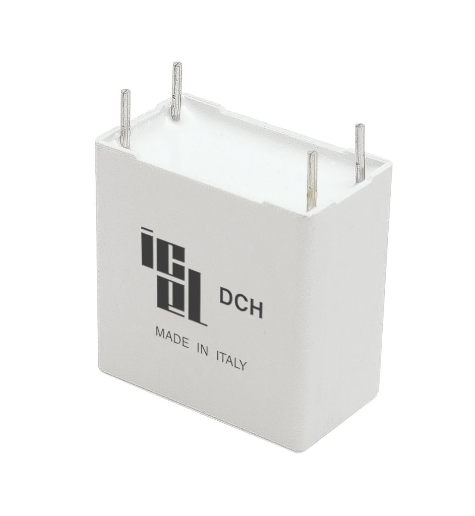
- DCH / DCS* – NEW! medium-high current, medium-high frequency, not suitable for AC, DCS: high safety version
- MHBS / MHBM* – high current, high energy density, MHBM only: suitable for AC applications and high Irms switching applications upon restrictions
- MHBA – Input/output AC and DC filtering. Suitable for high Irms switching applications. High frequency, high current
Boxed – LUGS execution
- MHBS / MHBM* – high current, high energy density, MHBM only: suitable for AC applications and high Irms switching applications upon restrictions
- MHBA – Input/output AC and DC filtering. Suitable for high Irms switching applications. High frequency, high current
*recommended
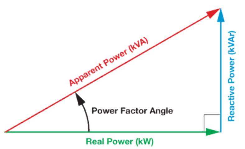
Capacitors for AC applications, by producing reactive power
- compensate for the reactive power consumption of electrical motors, transformers, etc. leading to more stable power with increased transmission capacity and reduced losses thanks to higher power factors
- constitute a key component in the various filter solutions that reduce harmonic content. A non-distorted sinusoidal voltage without harmonics reduces the risk of problems in the form of disturbances in production equipment, metering errors and malfunctions in relay protection. It also extends the service life of connected equipment
AC-Power capacitors are used in a wide range of applications
- inverters and converters
- motor control / drives
- motor run
- renewable energy (Wind, solar, …)
- traction
- UPS
- battery chargers
- elevators
- …
AC-Power capacitors are used in power supply circuits where noise suppression, voltage regulation and line current reduction
is required. These applications typically expose the capacitor to higher order harmonics
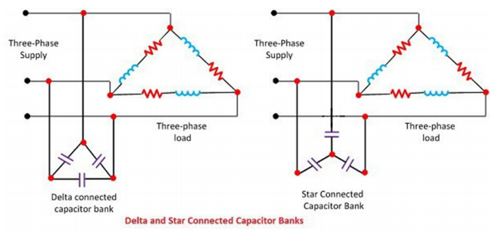
AC capacitors are also used in power factor correction circuits where they supply leading reactive power to correct the lagging current caused by inductive loads. The circuit is said to be running at unity power factor if the capacitive reactance of the applied capacitors exactly matches the inductive reactance of the load
AC capacitors are also used to provide the necessary starting torque to split phase motors by introducing a phase shift on a secondary motor winding. Motor-run capacitors also provide the necessary power factor correction during the run stage for a more energy efficient motor operation
Most AC-Power plastic film capacitors are designed with polypropylene metallized film material. Low-loss dielectric material, suitable for designing capacitors for use in both low and high pulse applications.
The properties of a plastic film capacitor are significantly dependent on the construction technology used, but a good capacitor for AC application shall have:
- low equivalent series resistance (ESR)
- low self-inductance
- high Irms and Urms ratings
- excellent mechanical stability
- high reliability with low/under control failure rate
- excellent self-healing capability
The above variables are defined for a specific frequency and temperature range
Surge or high pulse stresses, voltage fluctuations and other line disturbances are typical for Input AC filtering application.
Specific attention must be paid for the choice of the capacitors to be used
- the choice of the right capacitor is fundamental to avoid critical operating conditions and consequent possible failures
- if required by law, certified interference suppression capacitors must be chosen
Boxed – PINS execution
- MHBA* – Input/output AC and DC filtering. Suitable for high Irms switching applications. High frequency, high current
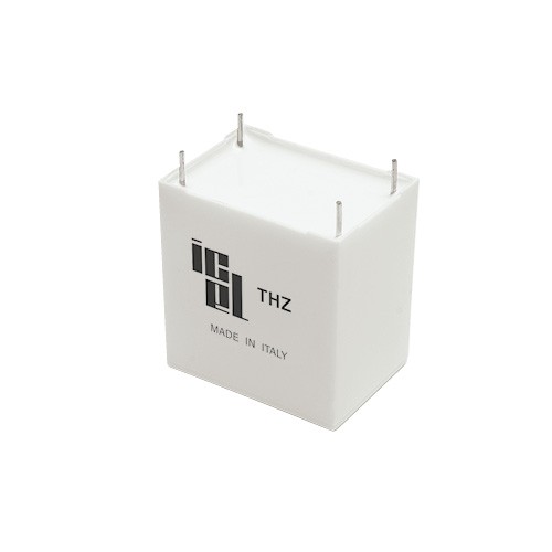
- THZ* – High performance and high reliability AC-Power, harsh environment (high temperature and high humidity level)
- MHBM – high current, high energy density, suitable for AC applications and high Irms switching applications upon restrictions (NO input filtering)
- MAB – AC-Motor run, MABA01 and MABA02 EN60252-1 IMQ approved, all types UL810 construction only approved (execution upon request)
Boxed – LUGS execution
- MHBA* – Input/output AC and DC filtering. Suitable for high Irms switching applications. High frequency, high current
*recommended
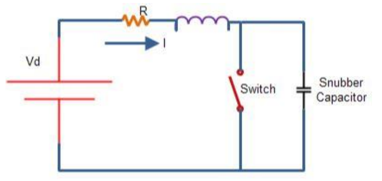
Snubber capacitors are essential in a power conversion circuit
The main function of the snubbers is to protect FETs, IGBTs and other switching devices from large voltage spikes, commonly produced during switching operations
The range of applications in which snubbers are used is very wide
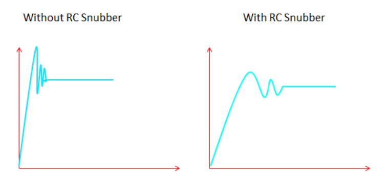
- reduction or elimination of voltage or current spikes
- limitation of the du/dt
- suppression of electromagnetic interference (EMI)
- losses reduction caused by switching operation
- shaping of the load lines
- transfer of power dissipation to resistors or useful loads
A "hard switching" operation subjects a switch to voltage and current stress and causes high switching loss. The presence of parasitic inductance increases this stress further.
The electronic circuits of motor drives, lamp ballasts, power converters, and other power devices may be different, but most have common switch-diode-inductor networks and waveforms: same snubber requirements since the behavior of the fundamental network is identical.
Most of today’s high voltage inverter circuits use IGBTs as the switching devices. IGBTs can switch high currents within short time frames, so they are exposed to potentially harmful voltage transients and therefore require protection circuits.
Snubber circuits are exposed to high stress, so the capacitors used in such circuits are subjected to and must withstand high du/dt and extremely high values of peak and rms current.
Plastic film capacitors are widely used for snubber applications, for both high power and low power circuits.
Most snubber capacitors are designed with polypropylene material. Low-loss dielectric material, suitable for designing capacitors for use in both low and high pulse applications.
The properties of a plastic film capacitor are significantly dependent on the construction technology used: polypropylene film/foil, metallized film and double-sided metallized film are commonly used as snubber capacitors
- lug terminals execution available for direct mounting on IGBT modules and busbars
- a combination of metallized film and discrete foil can also be considered
Polypropylene snubber capacitors offer high tolerance and stability, together with high voltage and current withstanding
- changes in temperature or applied voltage have minimal effects on the performance characteristics
- low and virtually linear temperature coefficient
- very stable capacitance
- low equivalent series inductance (ESL) and low equivalent series resistance (ESR)
Boxed – PINS execution
- PPR/PPB* – high performance, high pulse, high frequency
- PSB/RSB* – high pulse, high current
- PHS – medium-high pulse, high current
Boxed – LUGS execution for direct mounting on busbars and power modules (IGBTs, etc.)
- PMB/RMB* – high pulse, high current, low ESR
- PMS – medium-high pulse, high current, low ESR
Axial execution
- PPA* – high pulse
- PPS – medium-high pulse
- PWS – film foil snubber, very high pulse, low losses
*recommended
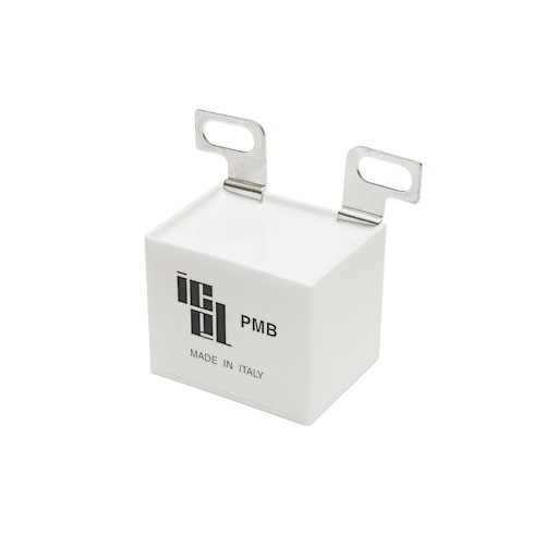
A capacitor operating in moist ambient absorbs humidity
Humidity enters from the leads-sealing and/or box-sealing contact surfaces and gradually reaches the winding
The humidity absorption can cause gradual electrodes oxidation leading in medium-long term to the capacitor damage or failure.
If voltage is applied, electrochemical corrosion may occur, destroying the metallization and causing capacitance drop, overheating, swelling of the capacitor’s body and potentially ending up to short-circuit and relevant damage up to explosion and burning. The potential related ageing effect strongly depends on the capacitor design and material, and on the amplitude of the applied voltage.
Capacitors eventually modify their characteristics according to environmental conditions. The magnitude and speed of the modifications depend on dielectric, design and protecting material. With special design and special insulation materials the speed of this process can be slowed, but not completely eliminated
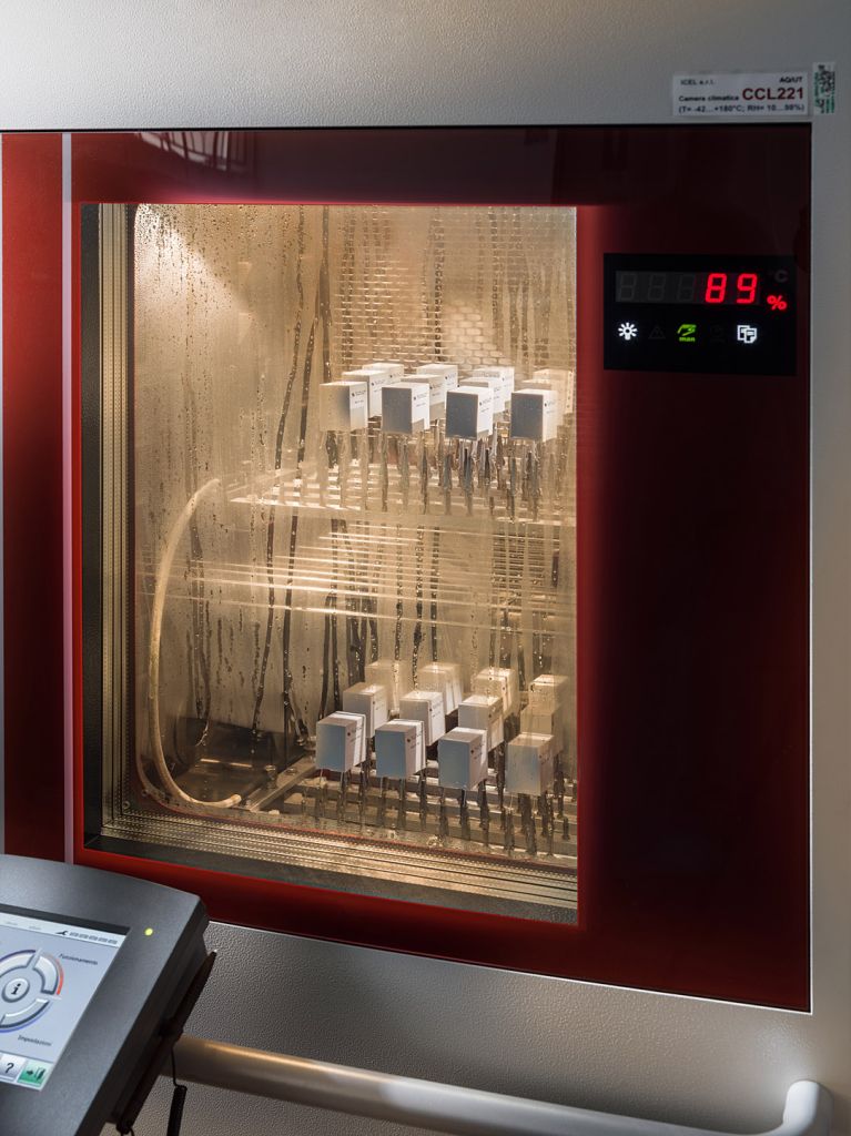
The combination of high operating temperature and high humidity levels, even more with AC voltage operation and with high energy density design is a particularly dangerous and critical situation. This causes a fast ageing of the capacitor, with related relevant main parameters variation, body distortion, decrease of the expected life and rapid increase of the failure probability
This possible critical situation shall be taken into account, in particular if units are supposed to be used in tropical countries or at critical environmental and climatic conditions
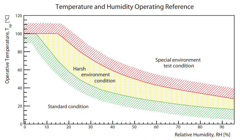
Most common tests adopted to evaluate high humidity and temperature performances for harsh environment are
- 40°C / 93% RH: standard damp heat steady state test (IEC60068-2; IEC 384-1; AEC Q-200 ref., cockpit, biased = voltage applied)
- 60°C / 93% RH: damp heat steady state test (IEC60384-17:2019, 56 days, Grade III high robustness under high humidity, biased = voltage applied)
- 85°C / 85% RH: extreme environmental condition of the THB (Temperature Humidity Biased) test. Very rarely reachable condition in real-life applications adopting film capacitors (IEC60068-2-67; IEC 384-1; AEC Q-200 ref., Level 1, biased)
Possible intermediate levels, usually corresponding to high stress levels but more realistic operating conditions and real usage
- 70°C / 70% RH; 60°C / 60% RH
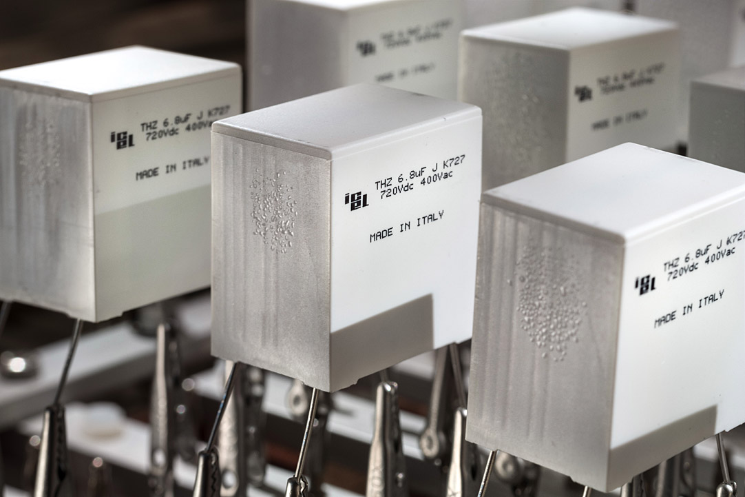
Testing capacitors upon the most severe test classes (85/85/1000: 85°C, 85% RH, 1000h), a typical effect could be the box bulging, even if with electrical parameters still within admitted variations and not corresponding to real electrical damages
THZ – this series represents a fundamental innovation and solution for power applications at operating conditions with harsh environments
ICEL S.r.l. R&D and technical office developed special materials design and execution to guarantee excellent performances in AC-Power applications up to high voltage ratings, combined with very good performances in harsh environments
Together with the high ratings and performances, THZ was also designed to guarantee reasonable dimensions and prices, compared to the existing AC-Power series
A slight de-rating of the maximum AC rated voltage ensures the AEC Q-200 85/85/1000 (Level 1) test compliance
THZ series also passes the AEC Q-200 cockpit test, the 70/70/1000 test and the IEC60068-2-67 humidity load test (Test Cy) at full ratings
The new THZ series is the starting point for the development of further new types which will complete ICEL S.r.l. offer for harsh environment applications
Rated votage (Ur):
it is the maximum direct voltage or the maximum rms alternating voltage or the peak value of pulse voltage which can be continuously applied within given ambient temperature range.
- When AC voltage is present, the sum of Vdc and peak Vac must not exceed Ur
- At high temperatures voltage derating must be applied
- The maximum admissible dissipated power must always be considered according to working frequency and temperature
- To ensure high reliability and long life, power capacitors should not be operated at maximum permissible voltage and maximum operating temperature simultaneously: suggested safety margins should be about 25÷30% lower than ratings
Overvoltage:
using higher voltages than rated may cause permanent damages
- Dielectric perforation
- Capacitance drop
- Insulation Resistance (IR) drop
- Short circuit
- Corona effect: high working voltage cause ionization called corona effect due to air trapped between winding layers. If the electric field in the capacitor exceeds the dielectric strength of air, micro discharges can take place damaging film metallization and/or the film itself. This typically causes capacitance drop but also overheating due to IR drop and ESR (Equivalent Series Resistance) increase , up to short circuit in case of persistent ionization
- In general lower reliability and shorter expected life
Always refer to what indicated at type specification about the voltages values and waveform applicable and allowed.
Always respect voltage ratings and choose capacitors having higher Ur than the working voltage to ensure safety margins and higher reliability.
Even if permissible AC voltages would cover lines voltages, ICEL S.r.l . capacitors for power applications are not certified nor suitable for across the line or line to ground applications (X or Y class)
Rated rms current (Irms):
it is the highest permissible rms value of the continuous current flowing through the capacitor at specified maximum case temperature
- The maximum Irms is given at certain frequency, typically 10kHz or 100kHz
- Power dissipation and related current derating must be considered according to operating frequency
- In pulse application with short pulse duration, also skin effect in contacts should be taken in account
- In specifications of capacitors series for power applications Irms ratings are typically, if not differently specified, referred to max ΔT of +15°C (T case - T ambient), operating at rated power, current and voltage, natural cooling ,≤+70°C ambient.
When working near rated maximum operating temperatures, due to power dissipation, the following maximum ΔT shall be considered for safety reasons (polypropylene capacitors)
- ≤10°C at +85°C Tamb in general
- ≤5°C at +85°C Tamb general purpose single metallized, not designed for power applications
As a general indication for rated max Irms
- ΔT around +10°C can be obtained applying Irms reduced to about 0.82 x Irms max
- ΔT around +5°C can be obtained applying Irms reduced to about 0.58 x Irms max
If nothing else indicated/permitted in data, avoid operating conditions causing relevant power dissipation at Tamb ≥+95°C (even if capacitor have higher rated upper category)
During stationary operation, the capacitor temperature must be always lower than the max operating temperature stated for the capacitor
Terminals can give limitations to capacitors max Irms rating or applicable current. The indicative max. current values by terminal style considered for ICEL S.r.l . power capacitor are:
- Tinned copper leads 0.8mm diameter = about 8A
- Tinned copper leads 1.0mm diameter = about 10,5A
- Tinned copper leads 1.2mm diameter = about 14A
- Lugs up to around 35÷40A depending on type and shape
Always refer to the specifications for the max. current and max. voltage capacitor can withstand and apply derating when required
The main effect of current flowing through capacitor is heating
- Together with ambient temperature Ttot = Tamb + ΔT it must remain lower than the specified max operating temperature
- To keep the Ttot under control derating can be required depending on the operating conditions
- Peak current flowing through capacitor causes localized heating on contact areas due to contact resistance between leads and capacitor element
- Heating extends to entire capacitor body, when pulse stress is repetitive. The combined effect of pulse and rms currents must be considered and maximum Ipeak and Irms values not to be exceeded
- Excessive heating reduces capacitor reliability and expected life and can cause deterioration up to short or open circuit, body deformation and melting with smoke emission and fire
Working at high operating temperatures can require voltage and current derating
- For any temperature between the rated temperature and the upper category temperature, the temperature derated voltage is the maximum voltage that can be applied
- Typical voltage derating for power capacitors, unless differently specified, are: Ur decrease 1,5% for every °C exceeding +85°C; Urms decrease 2,5% for every °C exceeding +85°C
- Irms is typically derated in relation to Tamb
- Testing of capacitor heating ΔT and Top (Tamb+ΔT) shall be made in conditions equivalent to the real operation conditions and by simulating the worst case working conditions
- Case temperature must be measured at hottest point, typically near the contacts/heads or on areas having poor dissipation capability because of external reasons like the presence of other hot components
Always refer to the maximum power dissipation admitted under normal conditions. It depends on many different factors such as:
- execution
- design
- shape
- dimensions
- materials
- ...
Not to exceed capacitors max. dissipated power and to avoid overheating, voltage and current derating must always be considered, as a function of temperature and frequency
Also ESR (Equivalent Series Resistance), as the sum of all that contribute resistivity (resistivity of electrodes, internal connections, dielectric losses, …) is a function of frequency: ESR = tgδ / (2πfC). The Dissipation Factor (tgδ or DF) is the power loss of a capacitor divided by the reactive power of the capacitor and it's too a function of frequency.
Please refer to "Harsh Environment" section for more details.
To summarize:
- Capacitor used in moist ambient absorbs humidity. This can cause gradual electrodes oxidation and in medium or long term capacitor damage or failure
- Capacitor eventually modifies characteristics according to environmental conditions
- The magnitude and speed of modifications depend on dielectric, design and protecting materials
- With special design and insulation materials the speed of this process can be slowed
- The combination of high operation temperature and high humidity (especially in AC operation) is a particularly dangerous condition, potentially causing a fast ageing of the capacitor with related relevant decrease of expected life and increase of failure probability
- Humidity can cause electrochemical corrosion destroying the metallization and causing capacitance drop, overheating, swelling of the capacitors and potentially ending up to short circuit and fire
Special attention should be paid when choosing capacitors to harsh environmental and climatic conditions
The reference reliability states a component type fraction failure under a defined load or operating condition. This fraction failure will not be exceeded within a specified operating time.
The reference operating condition for power capacitors to which the reliability and failure rate are referred, are the maximum ratings (rated voltage and rated temperature, without de-ratings applied and no humidity considered), unless differently specified at types specifications.
The Failure Rate is expressed in FIT (failure in time), as follows:
1 FIT= 1 x 10⁻⁹ / h (1 failure per 109 component hours)
The Failure Rate, when available, is referred to failure rate criteria like short or open circuit, main electrical parameters variation limits and so on, declared in each series specification.
Conversion factor CF can be used to estimate expected failure rate in different conditions. Please refer to General Technical Information document - paragraph B34.
The Lifetime Expectancy of the power capacitors series is, as well, typically referred to the rated voltage Ur and to the hot spot temperature of the capacitor case (the typical reference temperature is stated at type specifications).
The Life Expectancy may be improved derating the operating voltage and/ or the operating temperature.
Capacitors used in power applications are typically exposed to relevant stresses level and possible failure may result in very serious consequences. For this reason, the keeping of a wide safety margin (about 25÷30%) compared to ratings is a wise and long term profitable approach.
Life Expectancy can be expressed as a function of operating voltage and temperature. Please refer to General Technical Information document - paragraph B35.
The obtained estimations are based just on voltage and temperature parameters, NOT considering any other possible stress source, in particular the humidity level. Whichever is the obtained estimation, orders of magnitude higher than the reference value do not represent realistic data: keep a rational approach interpreting the result.
The failure rate estimation anyway prevails as a primary criteria to evaluate the reliability of the component The formulas shall not be used for estimations outside the specification rating limits.
To obtain long life and low failures incidence always consider large enough safety margins on ratings compared to application operating conditions, when choosing capacitors. The above information are referred to the typical behaviour of the single component, net the possible layout of several units connected in series/parallel, which may increase the global risk upon critical operating conditions.
Capacitor must not be installed in contact or very close to other components but with enough distance to allow proper airflow and cooling
- Contact to other components can cause mechanical stress under vibration or shocks or due to thermal expansion
Capacitors shall be placed away from any source of heating to prevent high temperatures to compromise design reliability
- The larger the capacitor is and the more it is stressed by voltage, current or temperature, the more important the correct design is
- Extra heating can also be consequence of strong magnetic fields inducing currents in metal parts
Capacitors shall be in safe distance from heavy current conductors
- The influence of other components must always be carefully evaluated
Leads, especially large section lugs, dissipate heat but can also transfer heat into the capacitor
- It is necessary to keep the connections cooler than the capacitor
Assembled circuits potting (i.e. resin sealing of the whole circuit) may significantly reduce the heat dissipation capability of the capacitors
- It is recommended to avoid it, unless carefully evaluated in the specific application
The washing of the circuit boards with solvents, liquids and cleaning substances may damage the protecting materials of the capacitors
- It is necessary to evaluate carefully and validate the cleaning process with specific tests in order to ensure the capacitor integrity